
PSiN Network Layer
Continuing with the implementation of PSiN, I have finally completed the development of a first version of a network layer. Based on an initial proof-of-concept using the updated PSIF, I could outline a basic implementation for the NET layer above the PSIF. The NET layer would basically have a receive call that used the PSIF receive interface(s), an analogous send call, a list of one or more PSIFs and a function to route packets between PSIFs based on a new logic addressing scheme. Addresses would be uint16_t, where each byte is an ascii value between 'A' and 'Z'. The higher (first) byte would be the network address, and the lower (second) byte the host address.
Design
But it soon became obvious this would take more than a few lines of code over the proof-of-concept, and definitely more functions would be needed. For instance, when the origin (using address AB) sends a packet to a destination terminal (for instance AC) that is in the same network (A0), we normally use "network specific routing", that is, the rule that tells which interface and next hop to use is applied to all packets destined to terminals in the A0 network, and, in our case that always means that the destination is on the same medium as the origin, so the action is to do a "direct send", with no other hops. We already know how to do this; this is precisely what the PSIF does... but to do that, the PSIF needs a physical destination address. The logical address helps the NET layer to choose the specific PSIF, and the physical address tells the LINK layer who the destination is. So we need a table that translates logic addresses of the same network to physical addresses. This table exists in the real world and is called, generally, a neighbor table or, more commonly in IPv4 an ARP (Address Resolution Protocol) cache.
Therefore, a major roadblock would be to overcome this necessity. The decision was: do I manually fill (or rather, expect the PSiN user to fill) the ARP cache at the time of using the library, or do I program an address resolution protocol for the PSiN devices to do this automatically? Well, to make PSiN useful for different audiences, I need to cover the use case where someone may study NET but not lower layers. Plus, sooner or later, address resolution will be a function that I want to teach with PSiN. So I decided to go the long way and program an address resolution protocol. You can see the details in the PSINET.h and PSINET.cpp files in the code (with_net directory). In a future blog post I will explain better the ARP implementation.
Another roadblock was that, whatever is above the PSIF needs to block on receive, that is, it must wait for the function to return when something is received. Having more than one interface, requires being blocked on more than one function. For that, I need to create a task per interface. But instead of giving the packet directly to the higher layer, these tasks first do some processing. If the packet received is a control packet (e.g. an ARP request), they may respond (ARP reply) and never relay the packet. Even when they do it, it is not to the higher layer, but to the main NET task.
The main NET task has a packet queue, which receives input from lower and higher layers. If a packet received from a PSIF is directed to the current node, it relays it to the higher layer, returning the PSINET.receive() function call. The higher layer must call again this function if it expects more packets (subject to a future TRANSPORT layer implementation of TCP-like and UDP-like protocols). If instead the packet is directed to another node, the PSINET object sends it over the new calculated route. Finally, if the packet comes from higher layers (from PSINET.send()), it is also send through the calculated route. By the moment, any device can act both as terminal and router, but I plan on making that optional, just like it is in most Linux distributions.
Test
I tested this on a setup with four nodes, shown in the image below:
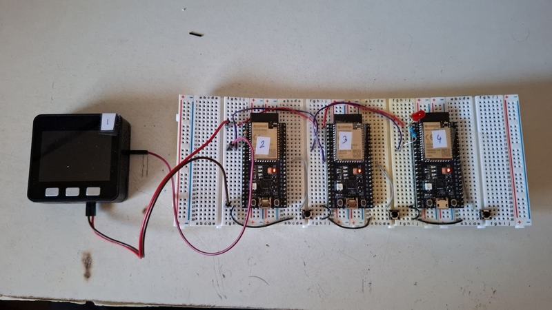
Node 1 is an M5Core ESP32 microcontroller, and nodes 2, 3 and 4 are ESP32-S2 dev kits. Node 3 is configured as a PSiN device with two interfaces (router.ino file), one at pin 5 (network A0) and another at pin 8 (network B0). And Nodes 1, 2 and 4 as terminals (terminal.ino). The addresses are as follow:
- Node 1: logical
AB, physical1. - Node 2: logical
AC, physical2. - Node 3
PSIF0(pin 5): logicalAA, physical3. - Node 3
PSIF1(pin 8): logicalBA, physical5. - Node 4: logical
BB, physical4.
Node 3 has the following code for configuring the routing tables:
RouteInfo lan_0;
lan_0.dest = NET_ADDR('A',0);
lan_0.next = 0;
lan_0.host = false;
lan_0.def = false;
lan_0.interface = &psif0;
lan_0.metric = 0;

RouteInfo lan_1;
lan_1.dest = NET_ADDR('B',0);
lan_1.next = 0;
lan_1.host = false;
lan_1.def = false;
lan_1.interface = &psif1;
lan_1.metric = 0;

RouteInfo def;
def.dest = 0;
def.next = NET_ADDR('A','B');
def.host = false;
def.def = true;
def.interface = &psif0;
def.metric = 0;

net.addRoute(lan_0);
net.addRoute(lan_1);
net.addRoute(def);
lan_0 is the rule for network A0, lan_1 for network B0 and the default is set (more or less randomly from my part) as a host specific rule to AB. This would be interesting if AB turned out to be a router (which it is not). Fun fact, there is not much more to the code than this for a router. Just add routes and it should automatically work!
The terminals have a very similar code for their routing tables:
RouteInfo lan_r;
lan_r.dest = NET_ADDR('B',0);
lan_r.next = 0;
lan_r.host = false;
lan_r.def = false;
lan_r.interface = &psif0;
lan_r.metric = 0;

RouteInfo def;
def.dest = 0;
def.next = NET_ADDR('B','A');
def.host = false;
def.def = true;
def.interface = &psif0;
def.metric = 0;
net.addRoute(lan_r);
net.addRoute(def);
Except that in terminal.ino we need some more code for using PSINET.send() and PSINET.receive(); specifically, the senderTask and receiverTask. senderTask is just a reimplementation of the original button monitor that polled the button and sent a packet when pressed, only now it uses PSINET.send(). And receiverTask blocks on PSINET.receive() and when something is received, it prints it out over serial.
With this setup, I was able to transmit data from AB (node 1) to BB (node 4) through node 3. The experiment also tested the ARP protocol, which was able in each step to obtain the PHY addresses.
What next?
In an upcoming blog post, I will make a video of the whole process, but not before designing some more practical nodes; breadboards are nice for small tests, but PSiN is now growing out that phase.