
PHY and LINK are now separate in PSiN
When a code base is young, we still have time to do foundational changes. You can do it because you really found limitations in your project, or because you are a perfectionist, or, in my case, a bit of both. But no matter what, you will hate every second of it. So now that I can sit down and write about these changes, I am happy to announce that they work.
Let's begin with why. In previous entries, I described the PSiN implementation at PHY layer, and the steps to improve it in order to be able to add a MAC LINK (let's use the formal OSI terminology) layer. Now, I could have just added the functionality of a LINK layer (flow control, error control, addressing and medium access control) as additional lines of code and call it a day. It would be easy, but not very pedagogical for code readers.
So I had to do this major refactoring of the code I am talking about. Most of the functions for sampling the line or writing voltages were moved to a new PHY class. The main functions are void write(const uint8_t* bytes, uint8_t len) and uint8_t read(uint8_t* frame), which, for all the PHY layer is concerned, just interchange bytes with the interface pin. They work, as seen in the last blog post, by using a preamble and a closing signal. len tells write when to stop writing, and read returns the read length. Both are meant to be called by the LINK layer, forming what we call a Service Access Point (SAP).
The LINK object contains some new functions, like more advanced send and receive functions: void send(const uint8_t* packet, uint8_t destination, uint8_t len), and uint8_t receive(uint8_t* packet, uint8_t* origin). As you can see, they have addressing built in. send will create a packet following a specific header structure:
Each header field takes exactly 1 byte (even ACK, although actually one bit is used; the rest is reserved for future use). Data can take up to MAX_PAYLOAD bytes (32 by the moment).
receive on the other hand, will ignore any packet not addressed to the configured physical address for the PSIF. But if a new frame is correctly received (a placeholder for checksum is also now part of the code), it will send an ACK (an empty packet with no checksum, length 0, but ACK set to 1).
The PHY and LINK objects contain the functions for passively reading and sending packets; in other words, they contain all the bit/frame/packet manipulation logic. But the actual operation of the interface is kept in the PSIF (PSin InterFace) object, like it was before. I have renamed sendAsync and receiveAsync to simply send and receive. Just like before, send puts a packet in a queue and receive waits on another queue, both operated from driverTask. A good representation of the current architecture of the system would be the following:
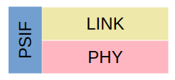
The PSIF object operates both PHY and LINK objects. And it will remain like this; I mean, so far I have no plans of extending the PSIF with network and beyond layers. Network should be a separate object that will be developed in the future; and higher layers too. But next steps will be to complete the long list of TODOs of the code, implement error management, and maybe MAC (but I may leave that for much later, where I can calmly study collisions and how to manually trigger them).