
First Proof of Concept of PSiN
After settling down the objectives for PSiN in my previous post, it is time to bring it to reality, at least the part in which we get two different devices to communicate and send bits. The objectives for this proof-of-concept will be very little ambitious:
- Create a simple object in Arduino that uses a pin to send/receive bits at a given bitrate.
- Create a program that:
- Listens for incoming messages over the line and reproduces them on the serial port.
- Sends bits when a button is pressed.
- Upload the sketch on two Arduinos and test them.
- Add a LED diode on the line to show the bits one by one.
The code for the proof-of-concept is hosted at the repository I created for the development of PSiN. The relevant piece of code is contained in the point_to_point_basic directory.
Main file
Within the directory, there is a point_to_point_basic.ino file, which contains the main program. Here we create a psif object in line 7:
PSIF psif(PSIF_PIN, BITRATE);
In setup() we just begin the Serial port and set the pin for the button. Then, in loop(), we start each iteration by listening for a packet by calling psif.receive(). If data is received, loop() is blocked until all bits are read. Once that happens, the received bits are showed over the serial using the previously defined printByteAsBits function. Next, we probe the button to check if it is pressed. If it is the case, we call psif.send(txMessage, 2), txMessage being a fixed message we defined early.
PSIF object
The PSIF (Pretty Simple Interface) object is defined in src/PSIF/PSIF.h as an object that contains all the implementation of a network interface. If we open the header file PSIF.h and implementation file PSIF.cpp, we will find the main send and receive functions.
send takes two parameters:
bytes: the bytes we want to send asconst uint_8t*.len: the number of bytes contained in thebytesparameter.
In the implementation, we can see that send relies on the writeByte function, which iterates over the bits of a byte and (through writeBit) sets the value of the PSIF pin to HIGH or LOW and waits for the bit time. send writes a preamble first (following the Physical layer definition), then the length in bytes and finally the contents of the bytes parameter.
The receive method will listen for a small time (settled at 0.1 x bit time), to see if there is a bit in the line. If there is nothing, it returns, in hopes that next time it is called, is less than 1 bit time later (this is a big leap of faith! but the objective at this moment is simplicity). In case there is, it will keep reading 7 bits more, and test whether the received byte is the preamble. In case it is, it will read the next byte, which is the size of the packet. Finally, it will read the bytes. receive returns a Result object, which contains the status (hasData), the length of the packet, and the data.
Circuit
To implement the proof-of-concept, two Arduino Uno shields have been used, albeit in a simulator. I used SimulIDE, a free and open source circuit simulator that can run Arduino sketches. You can also just use two physical Arduinos, should work just fine.
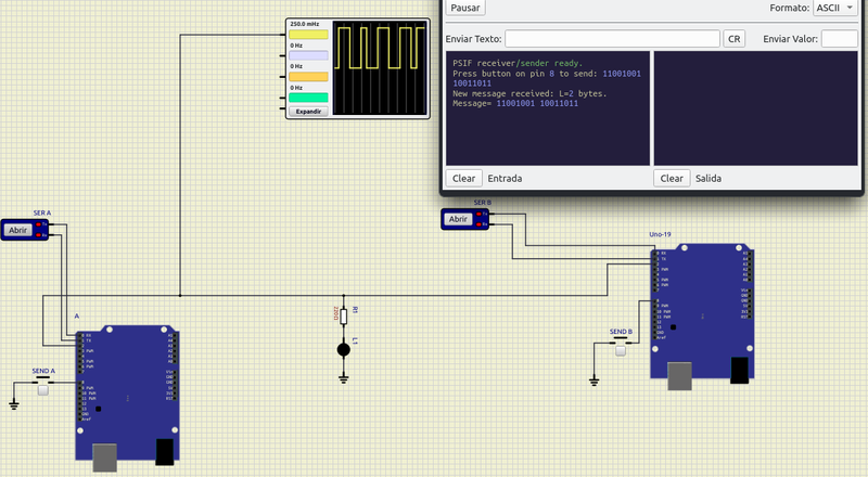
As you can see in the diagram, the setup is straightforward:
- The communication line connects pin 2 in both Arduinos. Since both are connected to the same virtual power source, no need for a GND line, but in a real setting with different power sources, this would be needed.
- Pins 8 connected to GND through a normally open button in both Arduinos.
- Serial terminal connected to TX and RX. In a physical setup, you would read the serial output over the USB cable.
- A complimentary LED diode + 220 ohm resistor connected between the line and GND.
Once the Arduinos are loaded with the firmware, just pressing the button in one Arduino will start the transmission of the message; two bytes in the case of this proof-of-concept. The result can be seen in the screenshot, where I added a virtual oscilloscope on the line, and opened the serial monitor of the receiver.
Next step
We now can see that the basic principle just works, and that the first version of the Physical layer has been validated. Next, I want to complicate things a bit, in order to simplify the code base long term; what I mean is I want to use FreeRTOS, such that I can implement much more complex tasks in the future for the higher layers, without having to carefully make sure that, for instance, we always sample the line on time and don't lose any incoming transmissions.